Copper and Aluminum Processing
Copper and aluminum respond differently to cutting, forming, bending, and handling. Manufacturing plans need to account for that behavior so interface geometry and contact areas stay controlled.
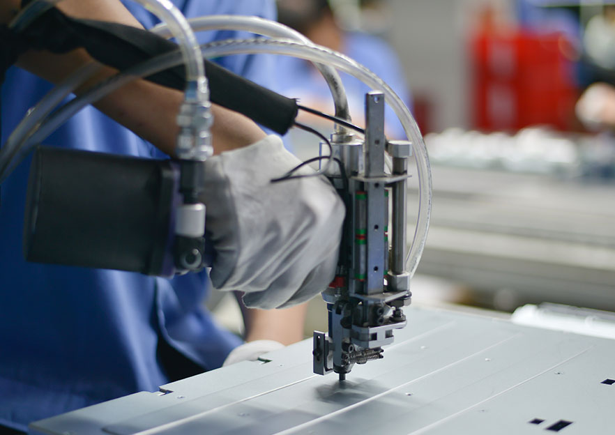
Energy Storage & Electrification / Busbars & Conductive Components
Lucky Harvest supports conductive components, connection hardware, and related assemblies with forming, joining, surface handling, insulation coordination, and repeatable interface control.
Manufacturing Strength
Busbar programs depend on controlled material behavior, contact geometry, surface condition, insulation boundaries, and repeatable assembly. Lucky Harvest coordinates forming, hole-making, surface handling, joining, and inspection so copper and aluminum conductive hardware fits, assembles, and repeats as intended.
Copper and aluminum respond differently to cutting, forming, bending, and handling. Manufacturing plans need to account for that behavior so interface geometry and contact areas stay controlled.
Bends, holes, slots, tab features, and contact zones are controlled as functional interfaces, not just features on a flat pattern. The goal is stable geometry across repeat production.
Fastened joints, inserts, brackets, covers, and composite connection details are coordinated so conductive hardware fits cleanly into the surrounding assembly.
Surface condition, coating or plating areas, insulation boundaries, masking, handling, and inspection discipline protect the contact and interface details specified on the drawing.
What This Includes
This work covers the mechanical layer of electrification hardware: conductive metal parts, connection features, brackets, covers, and interface hardware that must hold geometry while protecting surface and insulation requirements.
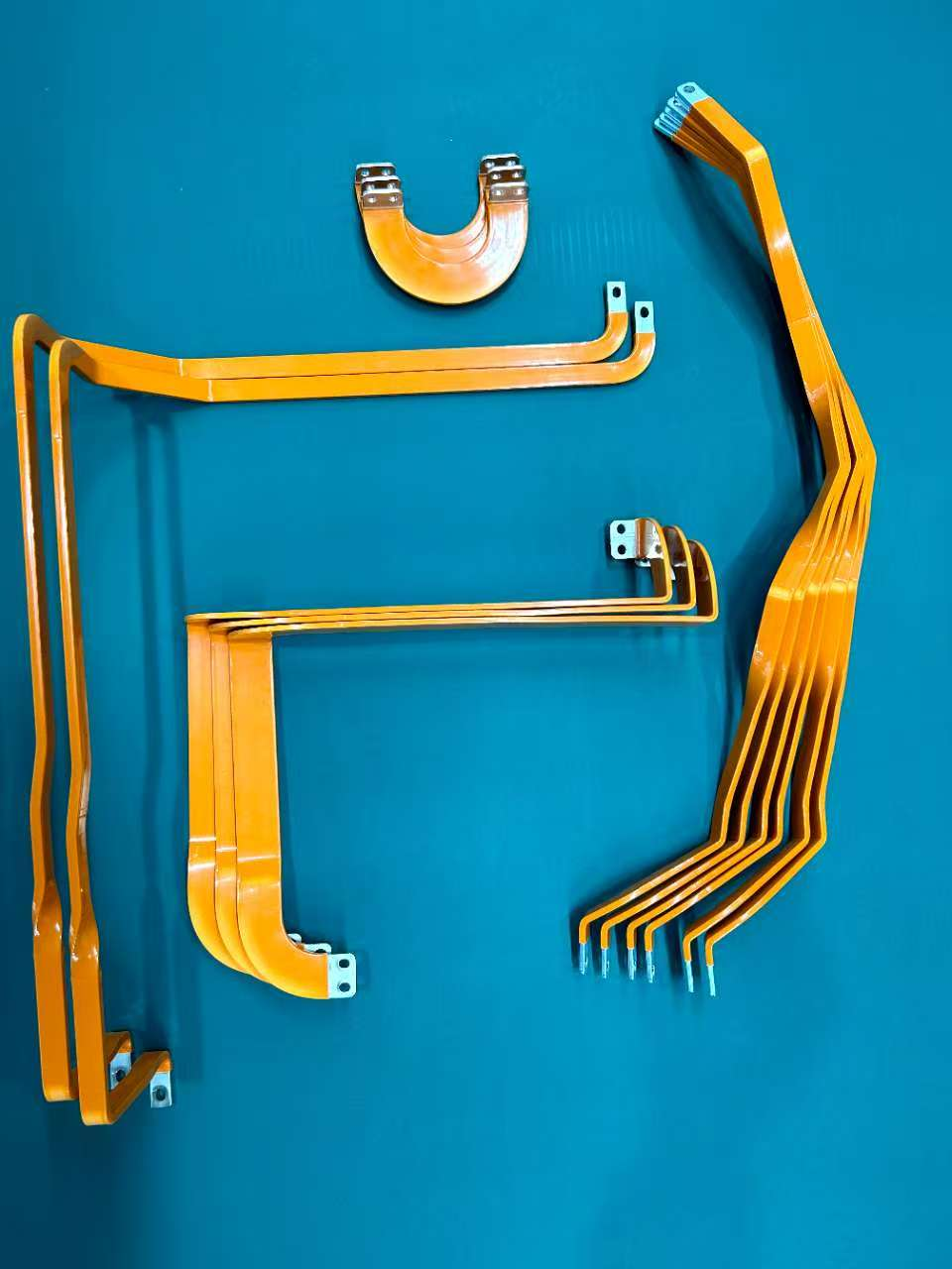
Rigid copper and aluminum conductive bars with controlled bends, cutouts, holes, and contact locations.
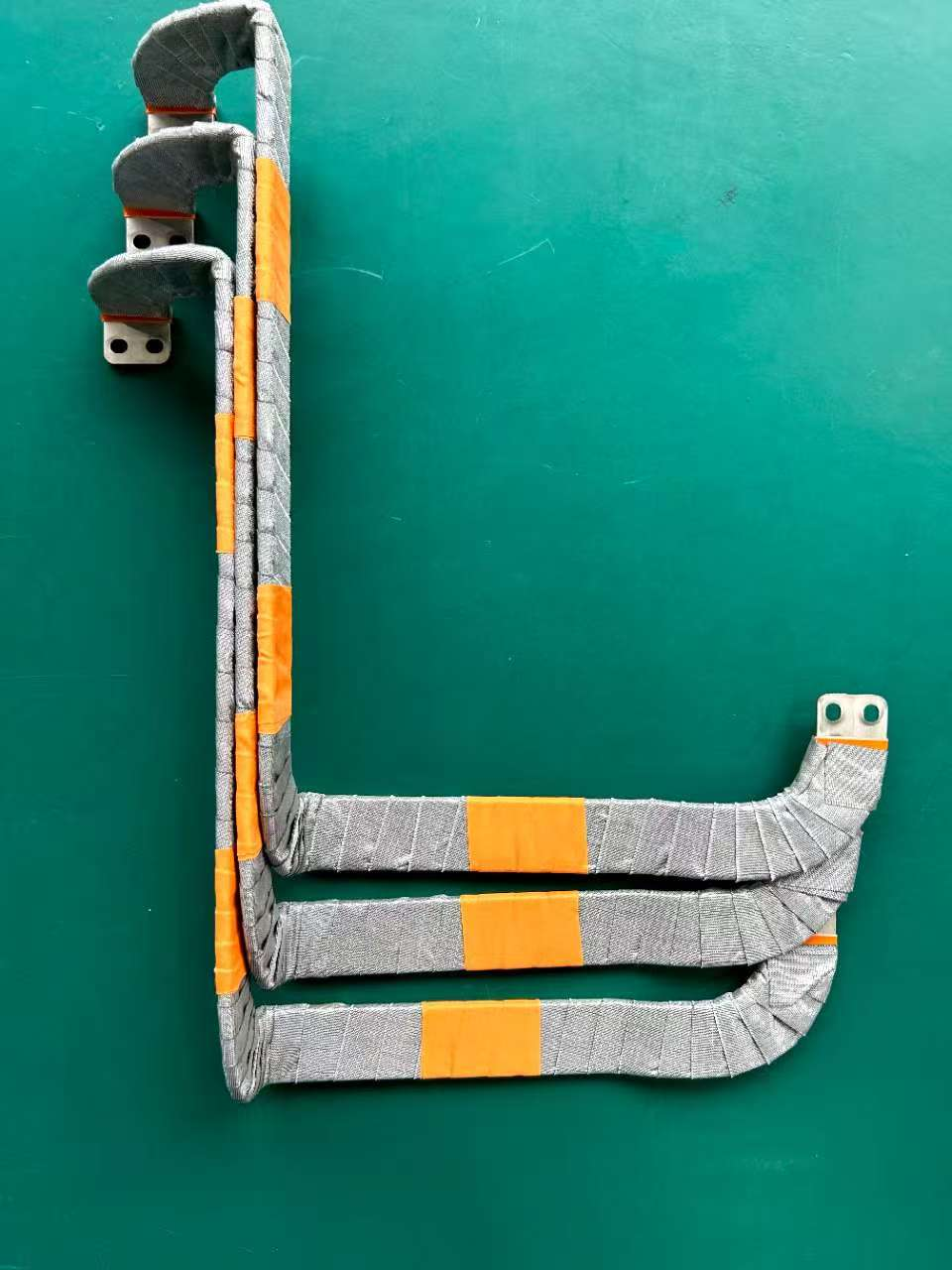
Flexible or laminated conductive structures where routing, bend behavior, material handling, and connection features have to be coordinated from the start.
Connection hardware that brings conductive parts, fastened interfaces, inserts, brackets, and covers into a manufacturable assembly.
Adjacent brackets, supports, covers, and insulating-interface parts that keep the conductive package mechanically organized.
Typical RFQ Inputs
Share 2D drawings, 3D files, connection geometry, hole patterns, interface locations, and assembly context so the manufacturing path can be reviewed against the actual package.
Identify copper, aluminum, clad, laminated, or related material assumptions, thickness, bend requirements, and part-family variation.
Note coating, plating, insulation, sleeve, handling, masking, and surface expectations where relevant.
Include fasteners, inserts, welded or joined features, brackets, covers, and assembly assumptions.
Provide target timing, estimated volume, inspection expectations, documentation needs, and qualification requirements.
Next Step
Send drawings, material choices, interface locations, surface or insulation expectations, assembly assumptions, timing, and quality needs. Those details give the team the context to align material behavior, interface geometry, surface expectations, assembly needs, timing, and quality requirements.